This is just to explain how I made my Kebiki marking gauge. You are always welcome to make it in your own way, and if you have any ideas on how to improve it, please don’t hesitate to share them with fellow woodworkers!
You do not have to use my kits, but they are available at the following link if you are interested.
-> Product URL – https://kittystationery.com/products/yrti-japanese-marking-gauge-kebiki-right-hand-kit
This will be shamelessly sold on KittyStationery.com ( https://kittystationery.com/ ) that is my wife’s hobby store for convenience:) There is no discount on these kits but if you are interested in Kitty goods, here is a 5% discount code: yrti25
* Sorry, all sales are limited to the US.
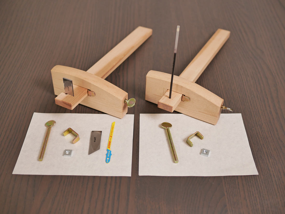
What’s Included in the KITs?
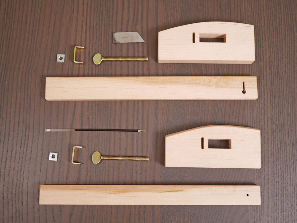
If you have ordered the Full Kit, all of the following items are included.
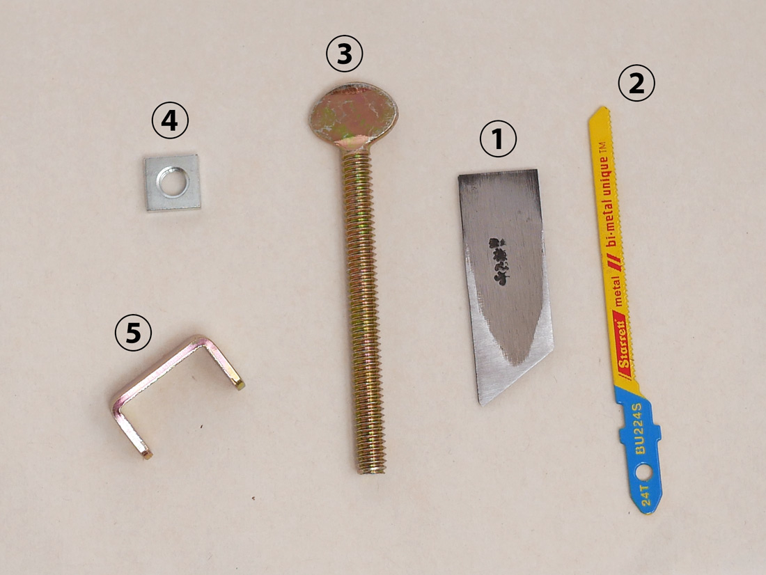
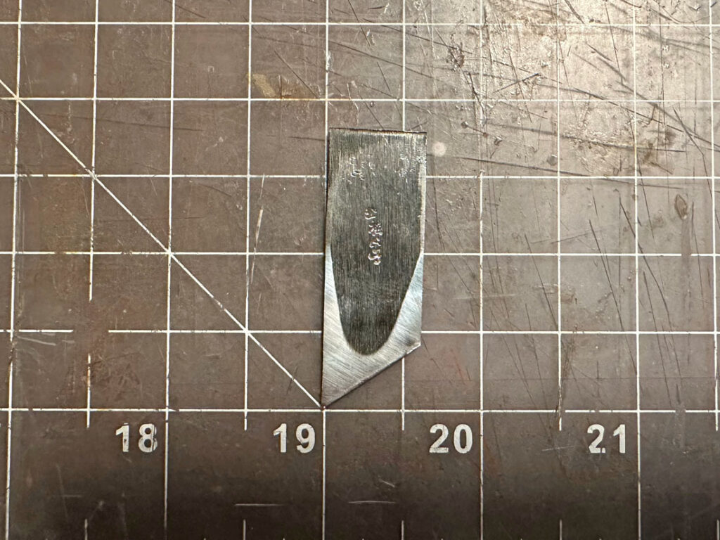
- Item #1 – Marking Gauge blade : Baishinshi/梅心子 Blade (Right-Handed, 15mm)
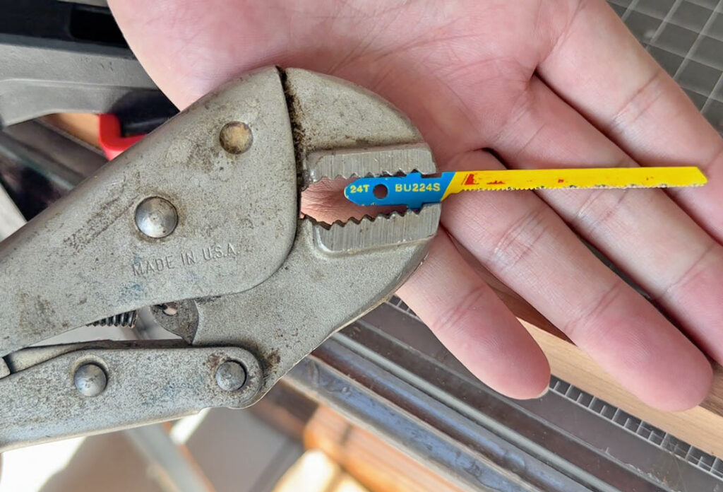
- Item #2 – Jig Saw Blade : Starrett BU224S x 1
- Item #3 – Thumb screw (Hardware)
- Item #4 – Square catch nut (Hardware)
- Item #5 – U-shaped bracket (Hardware)
The Hardware Kit contains only the hardware(Item # 3 to 5 on the above picture), meaning, no marking gauge blade and no jig saw blade will be included.
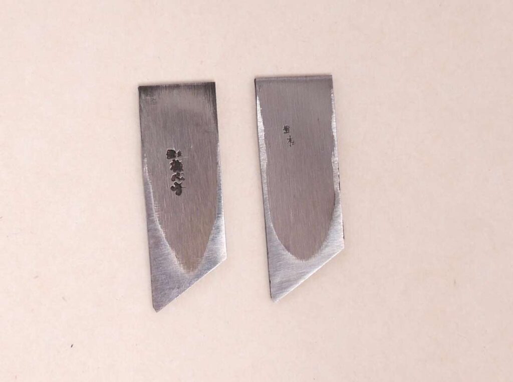
Please note, the blade is authentic Baishinshi but as in the picture, some of the blades do not have a clear stamp. Additionally, the hardware has some minor scratches from the manufacturing process.
*The included marking gauge blade is for right-handed use only. If you can source a blade yourself, the hardware can be used for both right and left hands marking gauge.
If you wish to source the blades yourself, Tsunesaburo and Mikihisa are available on Amazon Japan. The jig saw blade is included only with the Full Kit and if you want the jig saw blade, the one that comes with the Full Kit is the Starrett BU224S / Bi-Metal Unique Unified Shank Metal Cutting Jig Saw Blade.
Tools Needed
Standard woodworking tools, such as:
- Saws
- Chisels
- Drill bits (at least 1/8″, 3/16″, 1/4″)
- Hand Planes
- Sharpening Stones
Helpful Tools
- Drill block
- Flat, thin carving chisel
- Narrow, round carving chisel
- Diamon Plate
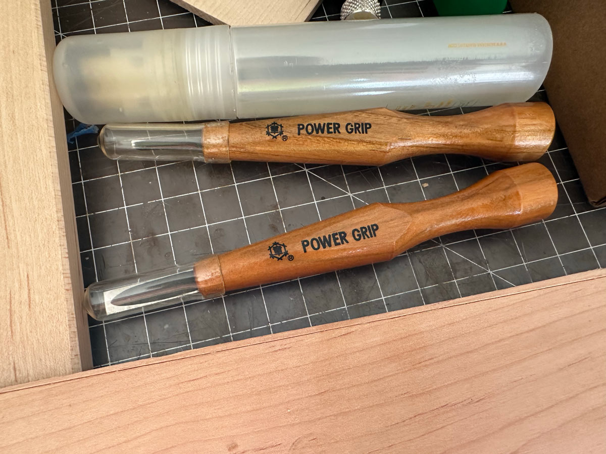
Specifically, I used Milescraft 1312 Drill Block, Mikisyo Sho Miki Power Grip Chisel Flat 0.3 inch (7.5 mm), Mikisyo Mikisho Power Grip Chisel Round (3mm) and POWERTEC Diamond Sharpening Stone (8″ x 3″ 150 / 600 grit).
PLANS and Instruction VIDEO
You can download the plans I created here:
- Plan A: For the full kit or a 15mm blade
- Plan B: For a common 9mm blade or a pencil/pen marking gauge
- Video Index
- 0:00 Introduction
- 0:44 Preparing Wood
- 1:58 Body Fabrication
- 5:37 Beam Fabrication
- 8:07 Preparing the Blade
- 10:17 Finishing Touches
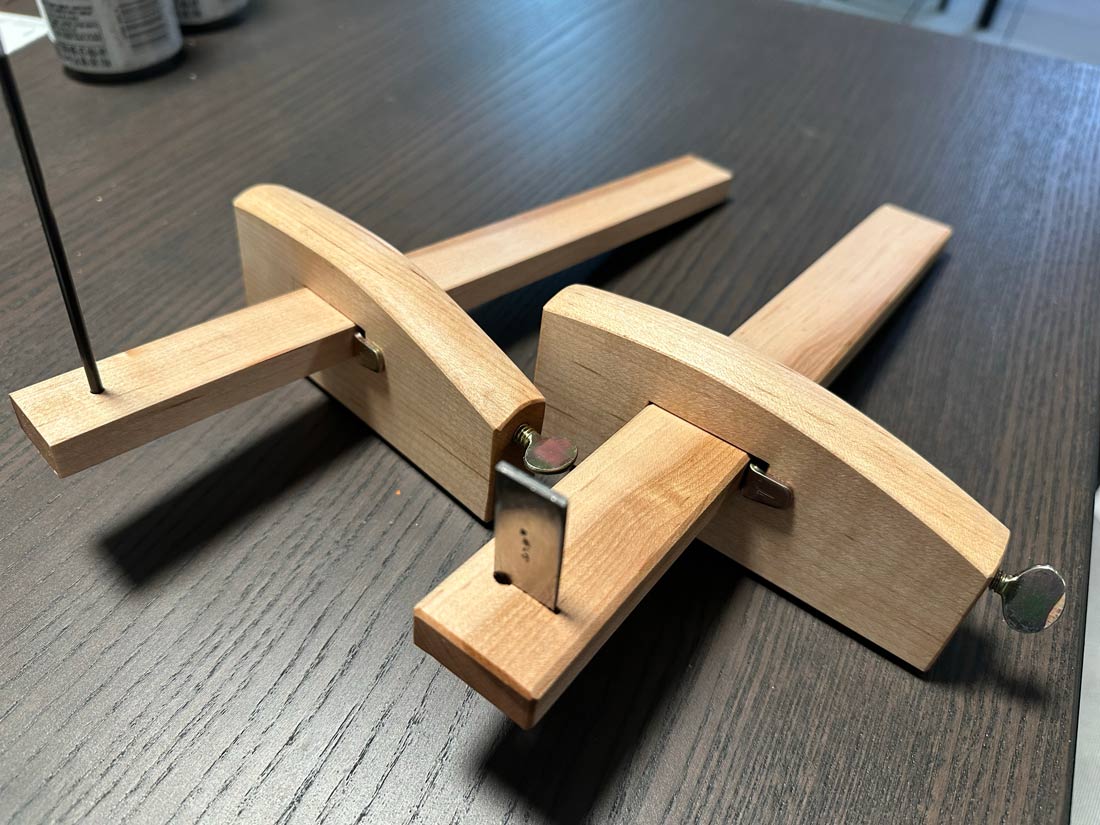
- 10:51 Final Product
- 11:10 Behind the Scenes Story
Choice of Wood & Grain Orientation
Wood Selection
Recommended: White Oak (ideally Rift Sawn or Quarter Sawn)
Ideal Properties:
- Hard and closed-grain
- Has a straight grain
Grain Direction
The grain direction is very important for a decent Kebiki.
Body
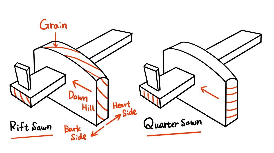
The body of the gauge requires careful grain orientation:
Rift Sawn: The bark side of the wood should be used for the reference face (the left side of the body where the blade sits). Additionally, ensure the grain runs downhill from back to front. This prevents the gauge from catching or “going against the grain” when slid along the edge of a workpiece.
Quarter Sawn: Unless the piece is perfectly quarter sawn, treat it similarly to rift sawn. Determine which side is closer to the bark side and use that as the reference face (the left side of the body where the blade sits). Again, ensure the grain slopes downhill from back to front for smooth sliding action. If the grain is perfectly straight, either direction is acceptable.
Beam
As long as you use the recommended Rift Sawn or Quarter Sawn stock, it’s all good.
Wood Preparation
If you are using a 15mm blade, Plan A provides the standard size. For the more common 9mm blade (typically found in a Kebiki marking gauge) or for a pencil/pen refill ink marking gauge, please use Plan B.
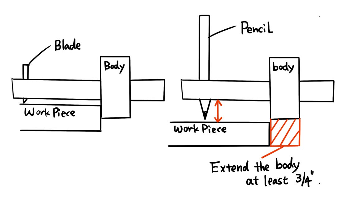
Note for Pencil Marking Gauges: If you are making a pencil marking gauge, you must add at least 3/4″ to the height of the gauge body’s bottom. As shown in the image below, a pencil requires more distance below the beam than a blade does.
Key Preparation Points
Body Thickness:
When preparing the body stock, aim for 13/16″ (which is approximately 25/32″). The final thickness will be achieved in the last step by planing the body, which also serves to clean up the wood’s faces.
Beam Thickness:
When preparing the beam stock, aim for approximately 9/16″ or a little less. The actual final dimension is 1/2″. You will achieve this final thickness in the last step by planing the beam while cleaning up its surfaces. Please ensure the thickness is consistent throughout the beam so that you only need to use the finishing plane to bring it down to the final 1/2″.
In addition, please also make the beam longer than the final required length. This extra length allows you to correct mistakes when cutting the slot for the blade: if you make an error on cutting the slot for the blade, you can simply cut off the bad end and re-cut the slot (each mistake will make the beam about 3/4″ shorter).
The U-shaped bracket for the beam is actually made for a 12mm (15/32″) thick beam. I designed the beam to be 1/2″ thick for convenience(and my personal gauge also uses the 1/2″ beam thickness). If you prefer the bracket to have less vertical play, you can change the beam thickness to 12mm instead of 1/2″, but you will need to adjust the height of the mortise and several other alignments needed accordingly.
Body Fabrication
Since you will not be gluing any parts, applying oil to the edge of your chisel before cutting a mortise can help soften the wood slightly, leading to a cleaner cut (I used camellia oil for blade maintenance, but a general finishing oil works well too).
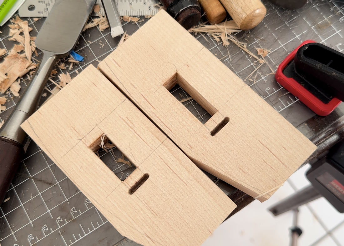
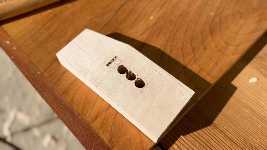
Cutting the Mortise for the Catch Square Nut
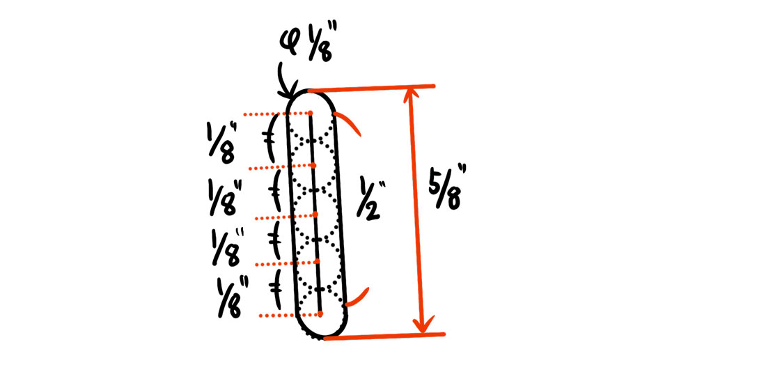
This 1/8″ (Width) x 5/8″ (Height) x 5/8″(Depth) mortise is the most difficult part of the fabrication.
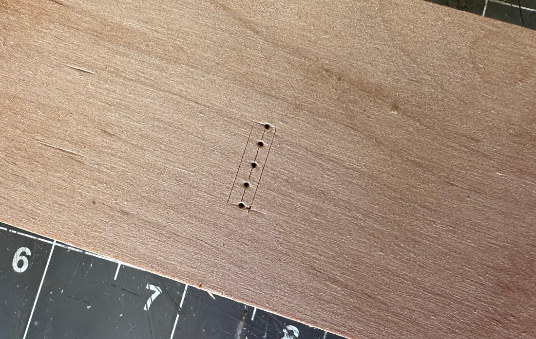
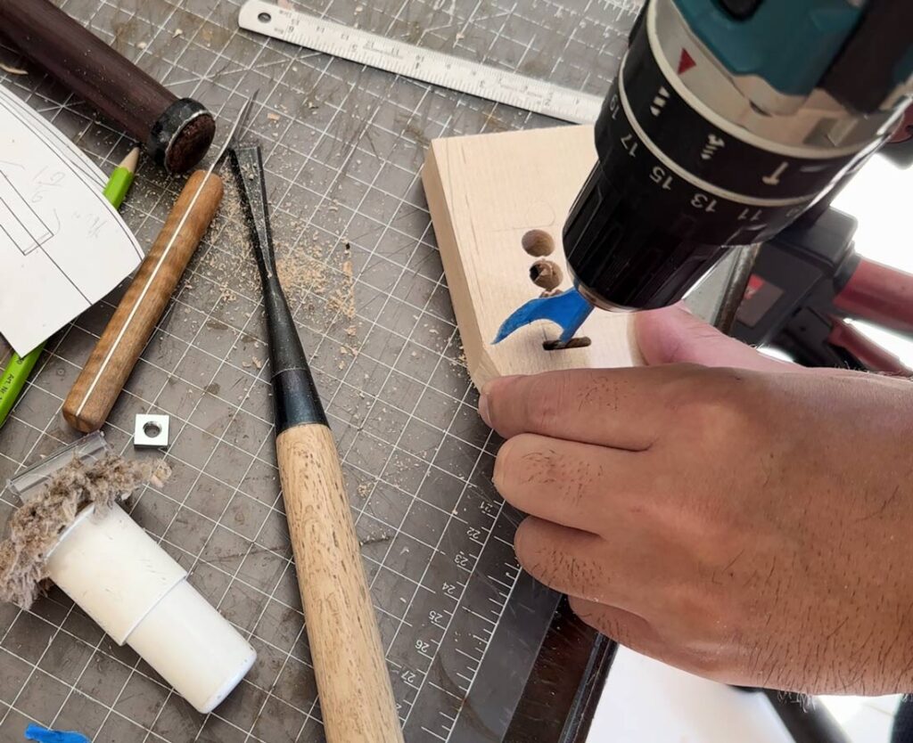
When drilling the relief holes, first mark the placement, and be sure to drill the holes on both ends of the mortise first. If you leave the ends until last, the drill bit may slip into the adjacent hole, making it extremely difficult to cleanly clear the ends of the mortise without a specialized cutting tool.
If it’s difficult…
Adjusting the Mortise Width : If the 1/8″ width mortise proves too difficult to cut, you can widen it. If you do this, widen the mortise towards the rear end of the body. Alternatively, you can make it a through-mortise (extending all the way through the body) so you can work on the mortise from both sides.
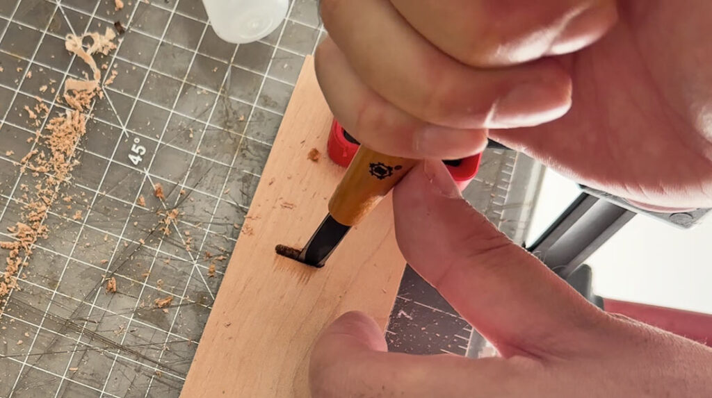
Helpful Tools: I used a regular chisel to clean the side walls and plunged a hand drill to clear the bottom of the mortise, but this was difficult. The process is much easier if you have a flat/thin carving chisel and an under 1/8″ round carving chisel.
Specific tools I found helpful – I also tried the Mikisyo Sho Miki Power Grip Chisel Flat 0.3 inch (7.5 mm) and Mikisyo Mikisho Power Grip Chisel Round (3mm), and they significantly simplified the work.
Cutting the Mortise for the Beam
The distance from the rear of the body to the front side of the mortise is critical because we cannot extend the length of the thumb screw. If the distance is too great, the screw will not be able to push the beam firmly against the front face of the mortise.
Furthermore, this mortise is deliberately cut wider than the beam width. The final width adjustment is achieved by using the screw to force the U-shaped bracket against the beam.
For advanced builders: you can make the front side wall of the mortise half-round (which means you leave the drilled hole intact). This makes cutting the mortise easier, but it requires that you also make one edge of the beam half-round, which demands a slightly higher skill level. The advantage is that this approach provides better beam security when tightening the screw.
Beam Fabrication
Layout and Cut
Please always mark the cutting line before drilling the hole. This ensures the cutting line and the hole center are perfectly aligned.
The overall slot length, including the hole, is 15mm. If you mark your cutting line 1/2″ from the center of the drill hole, this will result in a slot length that is approximately the required 15mm measurement.
Note: The hole should be 3/16″. This is the minimum size needed to initiate the saw cut with the included Jig saw blade, but if you have an alternative method for cutting the slot, a smaller hole is better for the marking gauge blade stability. The ideal slot width is approximately 1.6mm (a little over 1/16″). If you purchased the full kit, the Jig saw blade kerf provided is the perfect width.
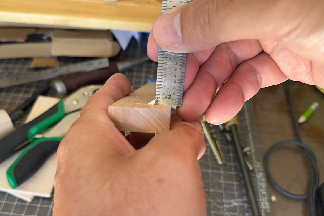
Key Technique: Setting the Marking Gauge Blade Angle When marking the line for the blade slot, use a protractor to set the angle to approximately 91 degrees. This angle ensures that the tip (the cutting edge) of the blade is slightly closer to the body than the other end of the edge, which helps pull the marking gauge toward the inside of the workpiece during use.
This means that even when marking on complex grain lumber, this angle, combined with the blade’s bevel, helps the reference face of the marking gauge body stay securely registered along the reference edge of your workpiece.
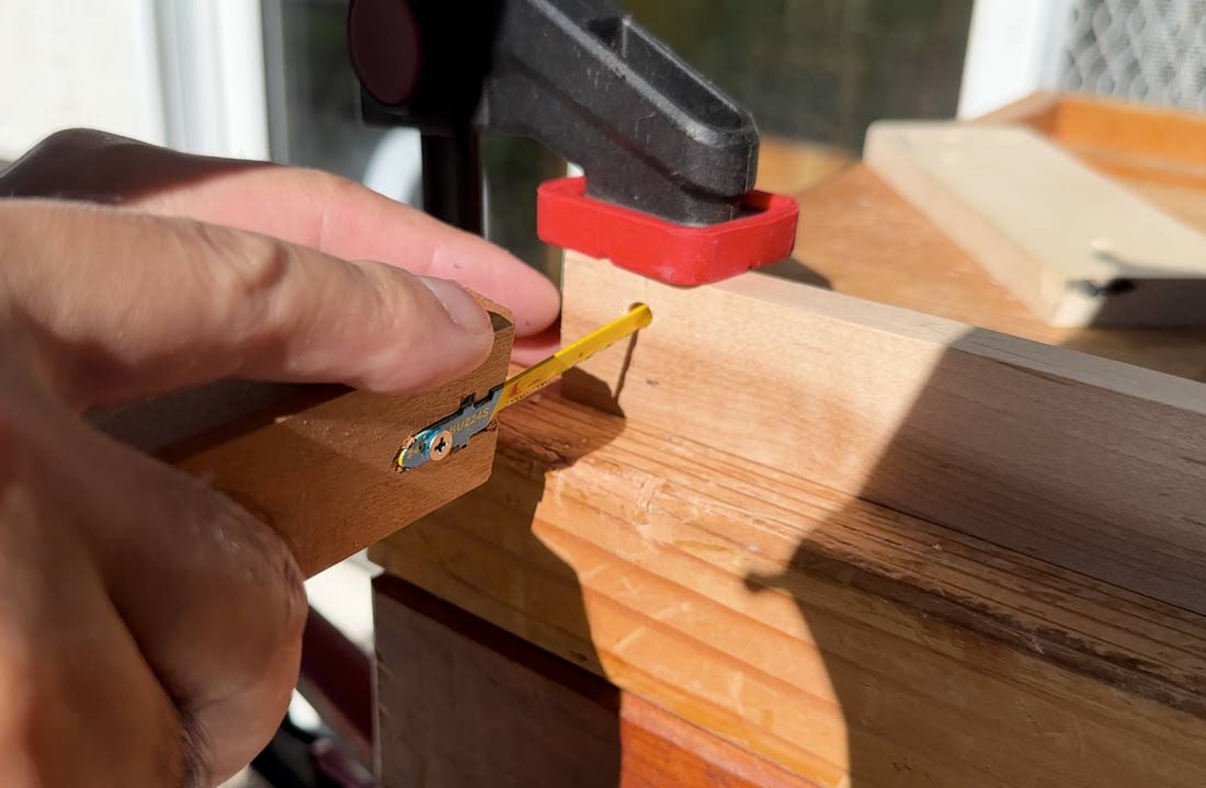
Testing the Blade Fit and Trimming
Once you have successfully cut the slot, you can gently hammer the blade in to test the fit. It is a success if about 1/8″ to 3/16″ of the blade tip protrudes cleanly through the beam and the blade feels steady. If the blade is not stable, you can cut off that end and try cutting the slot again. If the fit is good, you can now trim the beam to the final required length.
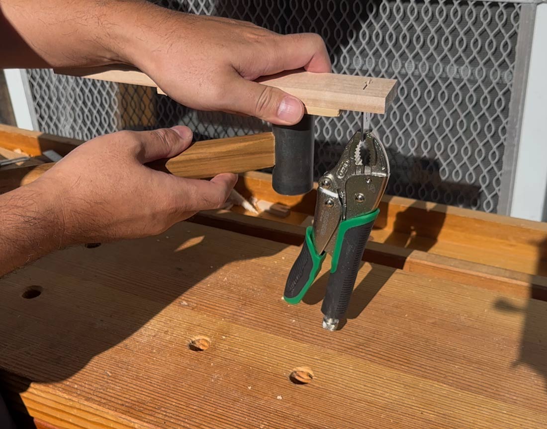
Removing the Blade
To remove the blade, you can simply tap the beam to loosen it. If it’s too hard to remove, use a vise grip to clamp the blade, then lightly tap the beam to loosen the blade before pulling it out.
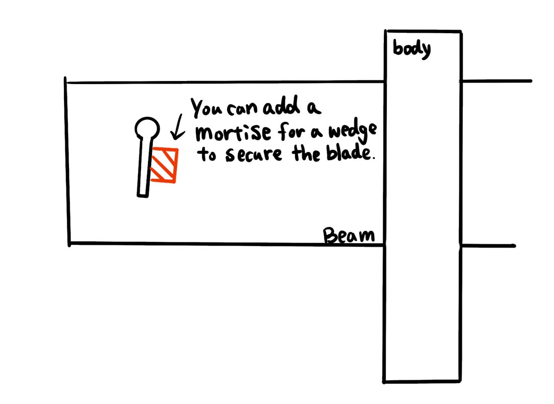
Long-Term Maintenance Note: If the blade becomes loose after prolonged use, you can widen the slot on the inside (the side facing the body) and insert a small wooden wedge to secure the blade. If you don’t mind shortening the beam, you can also cut it off to re-cut the slot instead of using the wedge option. The wedge option is also a good solution if you cannot achieve a perfect initial fit of the slot, too.
Preparing the Blade
Baack Prep
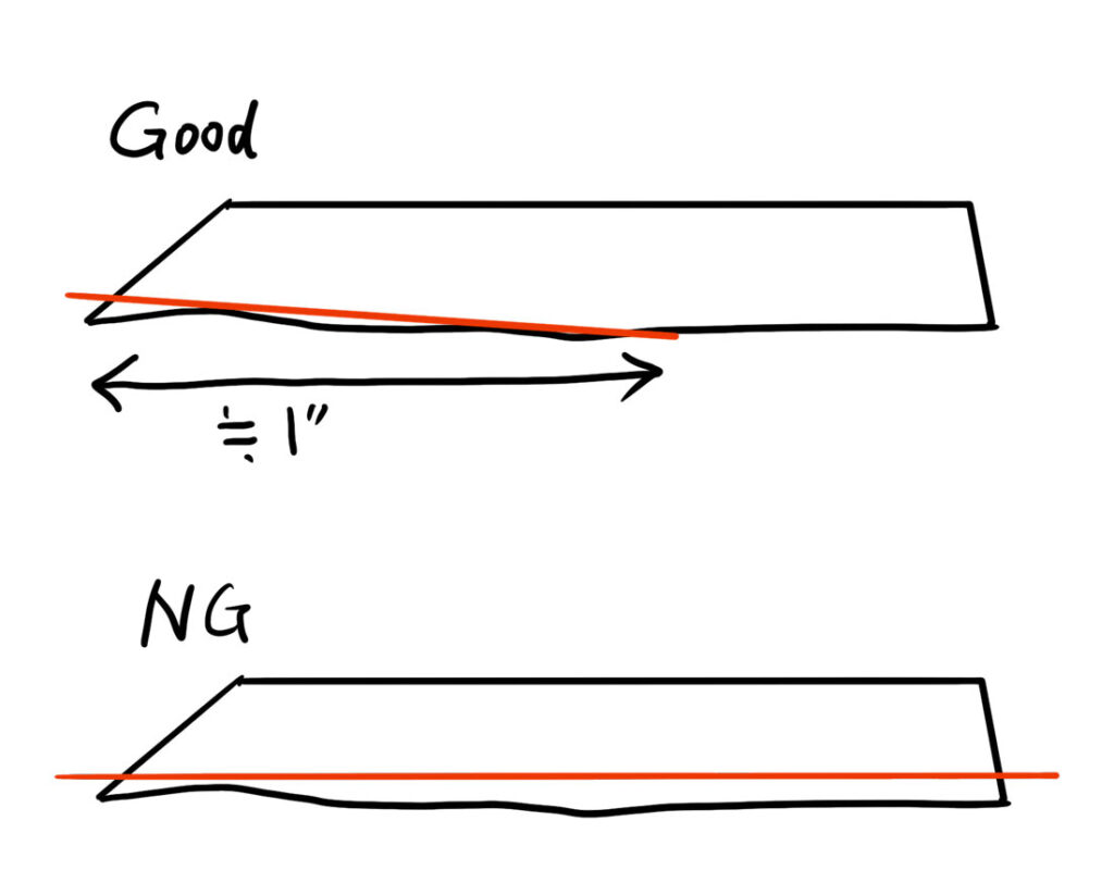
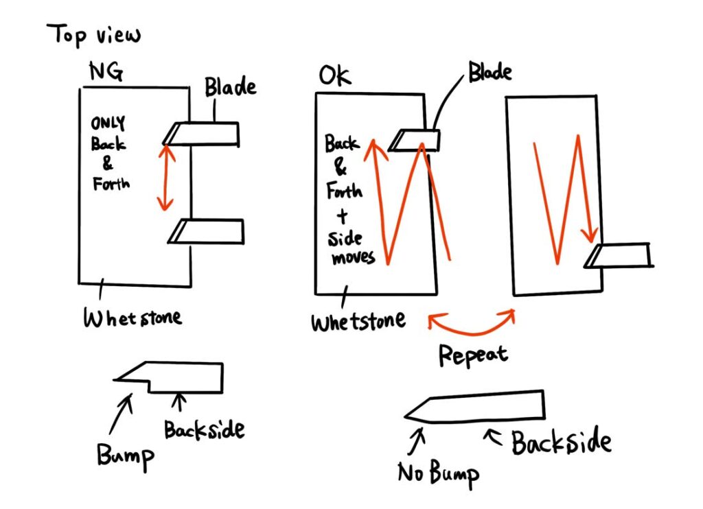
First of all, the back side of the blade needs to be flattened. It does not have to be completely flat across the whole surface, but if about 1/8″ from the cutting edge is flat, it is sufficient.
The ideal way is to apply pressure on the cutting edge of the blade to achieve the profile shown in the picture below.
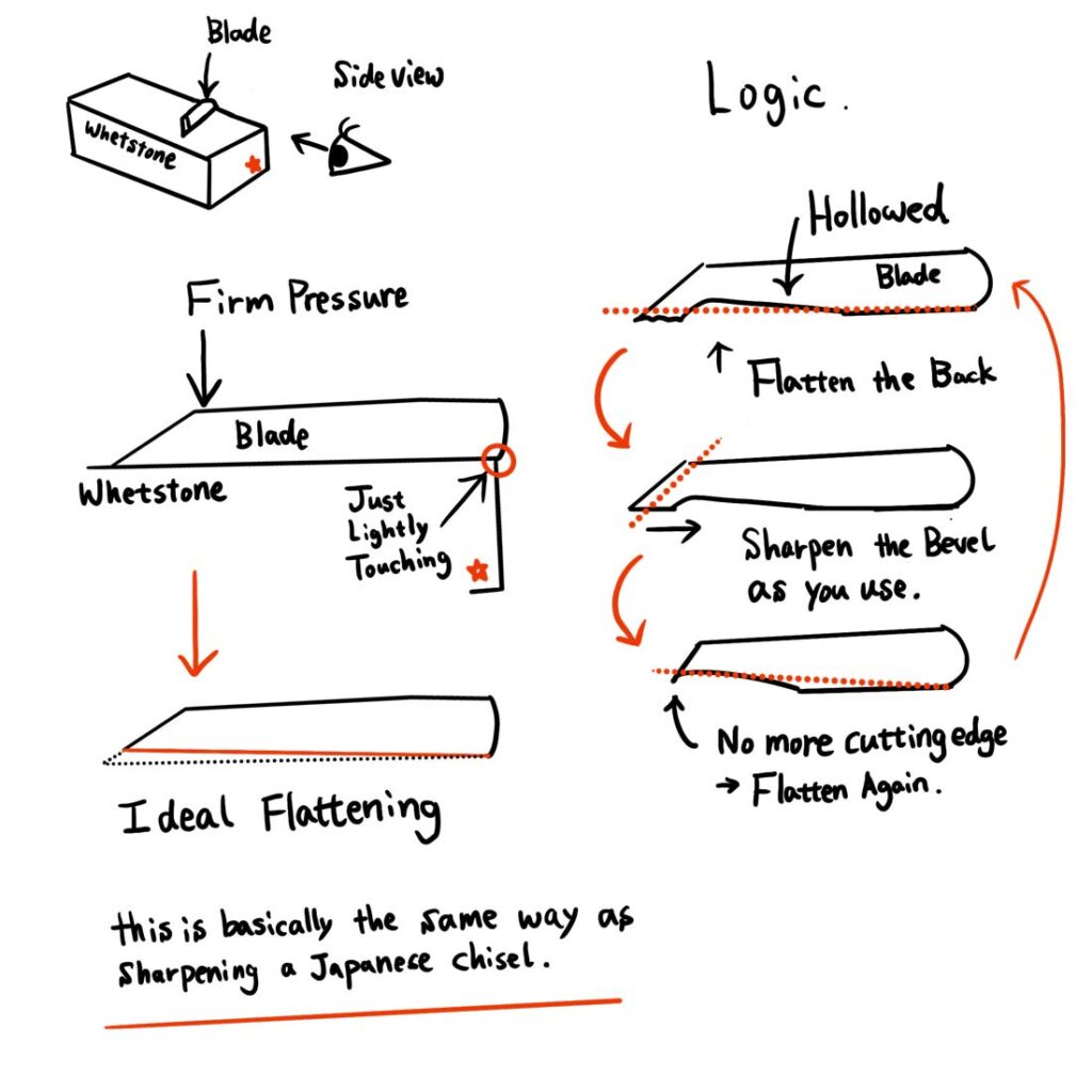
*As you use and sharpen the bevel, the cutting edge will eventually near the hollowed section. At this point, the back side should be flattened.
If it’s difficult…
Moving the blade side to side while simultaneously moving it back and forth will help flatten the tip without creating a bump. Please do not place only 1/8″ of the cutting edge down and move back and forth. This will create a bump on the blade.
Sharpening and Polishing
Once you have flattened the back side, you can work on the bevel. For the polish, it does not need to be a super high grit, but something around 3000 grit is good. If you do not have that, you can strop it after using 1000 grit. Then, work on the bevel.
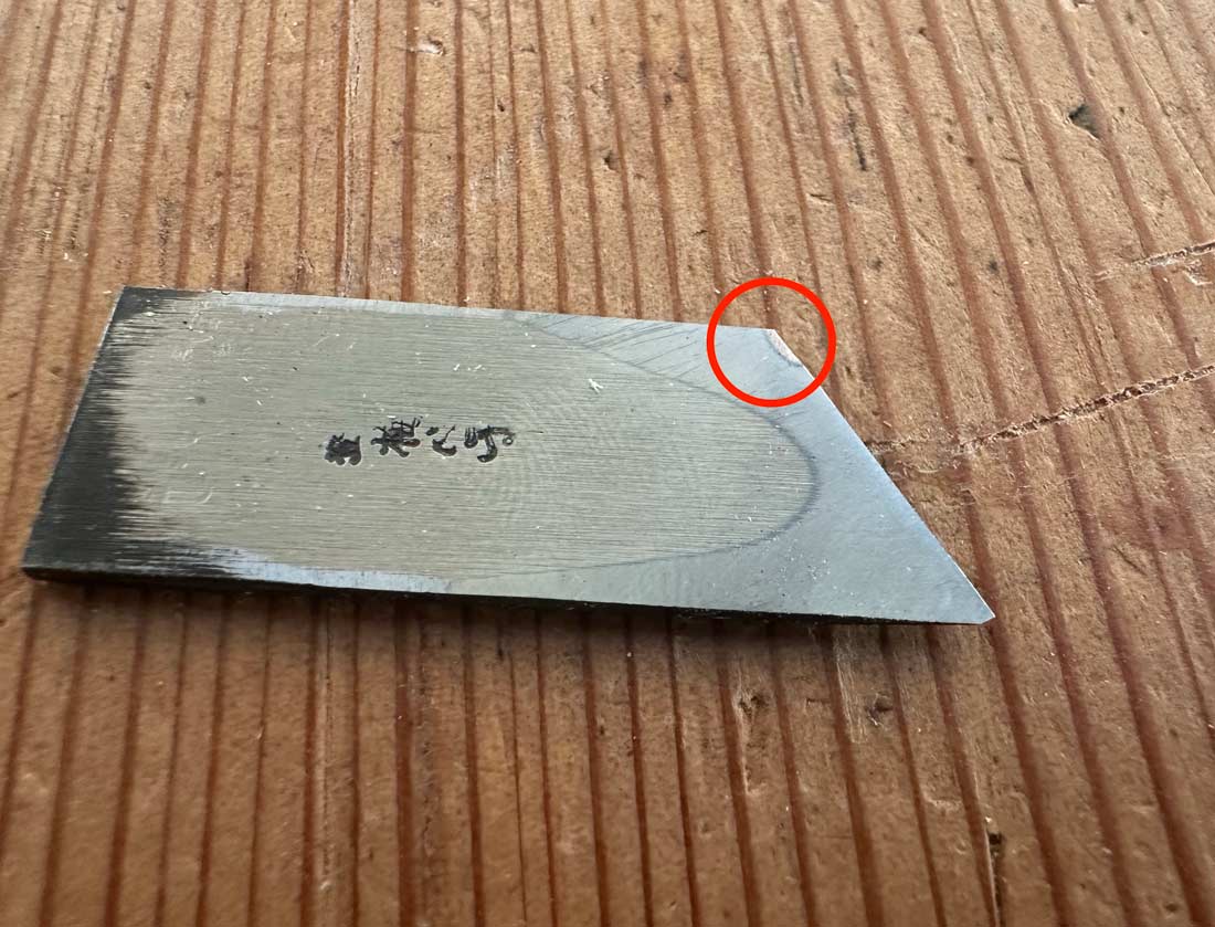
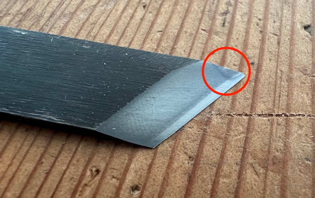
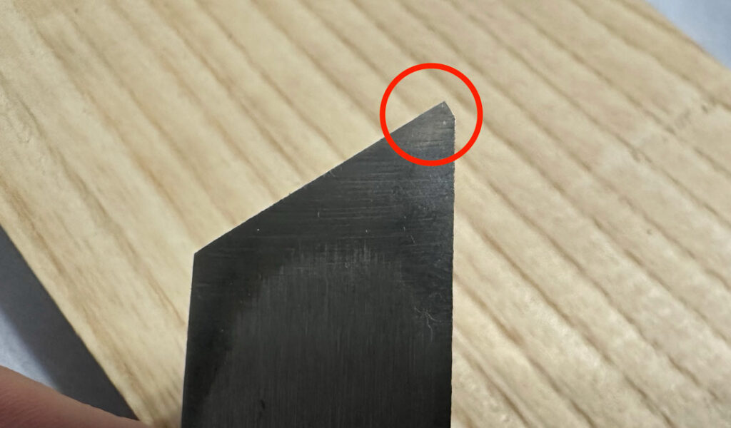
A Little Bit about Japanese Blades
Mineoroshi: The very tip of the blade may look slightly chipped, but it is not. This tiny cut-off is called Mineoroshi and this is intentional. This helps the pointing edge last longer without breaking.
Japanese Hand-Forged Iron: Sometimes, Japanese hand-forged iron is brittle up to about 1/16″ from the edge, meaning it may chip. This is unfortunate but is a common occurrence. You will need to grind down any chipped part. However, since you only need to use a small area around the tip of the blade, it should not matter even if the other end of the cutting edge is brittle and chips.
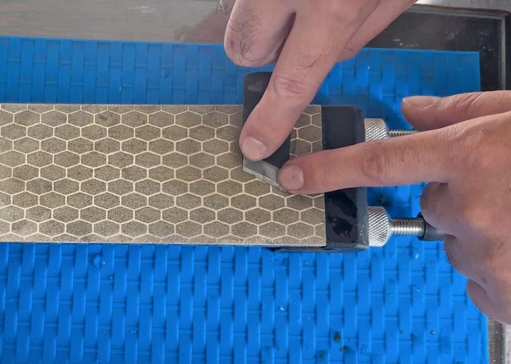
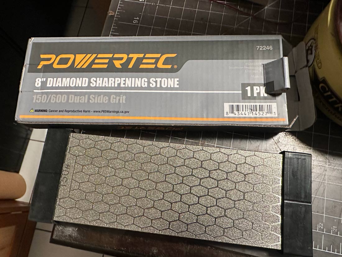
Diamon Plate Option
I use the Atoma #140 diamond plate, which is excellent in terms of flatness. However, its price is now almost $100, which is too much if you just started woodworking so I tested several reasonable options:
- DMT (8″ x 3″ Coarse)
- SHARPAL 168H (8″ x 3″, 220 / 600 grit)
- POWERTEC Diamond Sharpening Stone (8″ x 3″ 150 / 600 grit)
The most economical(Less than $25) option, the POWERTEC, was the flattest. I am unsure of the quality difference among individual units of the same product, but it is a good purchase.
Finishing
Adjusting Thickness
Body Adjustment: First, use a plane to adjust the thickness of the body to fit the U-shaped bracket. If you are not confident enough to create a flat surface with a plane, you can always use sandpaper on a known flat surface and ensure at least the reference face is flat.
I used to use Taytools 773420 One Piece 5/16 x 3-1/4 x 8-1/4 Dead Flat Float Glass. I found it effective because it is compact to store and reasonably priced.
Beam Adjustment: Next, use a plane to adjust the thickness of the beam so it fits smoothly into the body mortise. A tiny bit of wobble is acceptable since you can secure and tighten the beam with the thumb screw.
Final Touches
Finally, be sure to chamfer all the hard edges on the gauge. You can now apply oil or wax to finish the wood.
My friend also suggested to make a blade guard like a leather wrap to protect the cutting edge under the beam when not using as it’s so sharp.
You can find more pictures from here